Custom Design and Fabrication
Categories Products Center
Contact us
ZHEJIANG JHENTEN MACHINERY CO.,LTD.
Tel:+86-577-86867777
Fax:+86-577-86810195
E-mail:info@jhenten.com
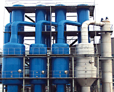
Mechanical Vapor Recompression (MVR)

Request Quote
Overview
MVR Overview
MVR is the abbreviated form of mechanical vapor recompression. This is a technology that recovers the energy of the secondary vapor it generates and therefore reduces the demand for external energy. As early as in 1960s, Germany and France have applied this technology successfully to chemical, pharmaceuti
MVR Know-Why
When mechanical vapor is re-compressed, the mechanically driven compressor will compress the secondary vapor generated by the evaporator to form a higher pressure. In this sense, the compressor acts as a heat pump to increase energy to the vapor. In another word, in this process, the low-temperature vapor is compressed by the compressor to improve its temperature and pressure and increase its enthalpy and then flow into the heat exchanger for heat exchange and condensation so as to make use of the latent heat of the secondary vapor. Except machine startup, no generation of additional vapor is required during the entire evaporation process.
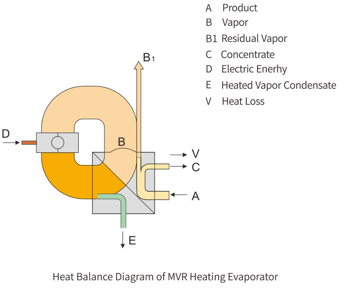
MVP Heat Balance Diagram
The Reason to Use MVP
·Low energy consumption per unit
·Gentle evaporation due to low temperature
·Short retention time due to the frequently Used single effect
·Simple process and high practicability
·Excellent service performance at some loads
·Low operating costs
Technical Characteristics
1.Low energy consumption, low operating costs;
2.Small space occupation;
3.Requires fewer public utilities and less total investment;
4.Stable operation and high degree of automation;
5.Requires no primary steam;
6.Short retention time due to frequently used single effect;
7.Simple process, high practicability, and excellent service performance at some loads;
8.Low operating costs; 9.Capable of evaporating at and below 40℃without any refrigerating plant and therefore particularly suitable for heat sensitive materials.
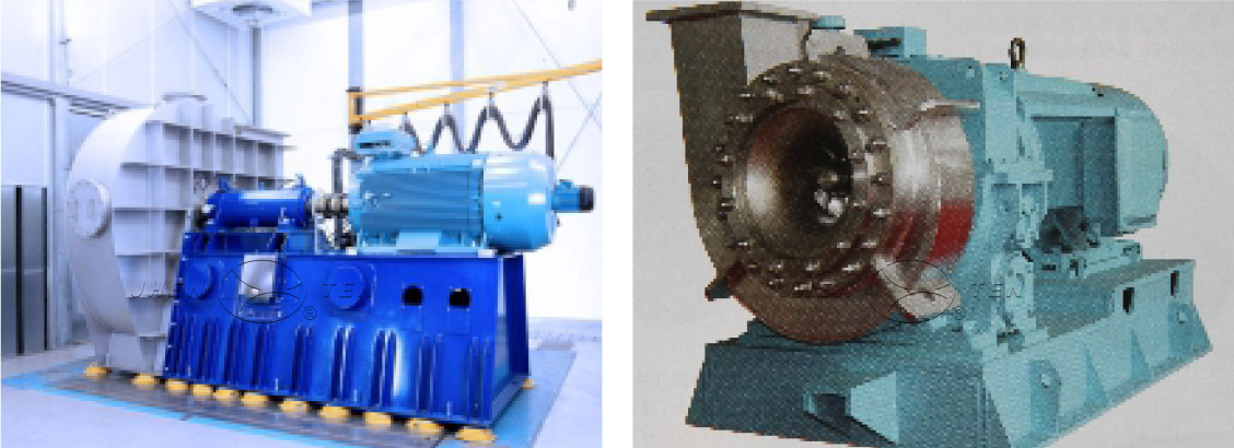
Design and Functions
Vapor compressor currently sued for MVP technology has two forms: the positive displacement type and the centrifugal type (i.e. speed type).Among positive displacement compressors, the most commonly used compressor is the Roots compressor which compresses gas by bringing two (or three) lobed rotors to relative motions in the cylinder. This kind of compressor keeps two rotors engaged with each other by relying on synchromesh gears located on the rotor axle ends; the curved surface of each concave on the rotor, together with the inside wall of the cylinder, forms a working displacement, which carries away the gas from the gas suction port during rotor rotation; when the carried gas moves to the vicinity of the exhaust port, the pressure in the working displacement will abruptly pick up at the moment it is to connect with the exhaust port due to the return of gas at higher pressure; and the gas then is delivered to the exhaust passage. This compressor has a large pressure ratio and a small sucking rate.Centrifugal compressors provide gas energy by means of high-speed rotation of impeller blades. In these compressors, the gas is accelerated and then passes through the diffuser at downstream of the impeller to decelerate. In doing so, the kinetic energy is transformed into pressure energy. According to the direction of fluids passing through the impeller, these compressors are named axial flow, mixed flow, or centrifugal compressors respectively. They are renowned for large pressure ratio, big flow rate, and good stability. Whichever is the most suitable compressor depends on specific operating conditions and the economy of the entire system. Critical parameters include the pressure rise to be achieved and the volume flow of steam to be compressed.
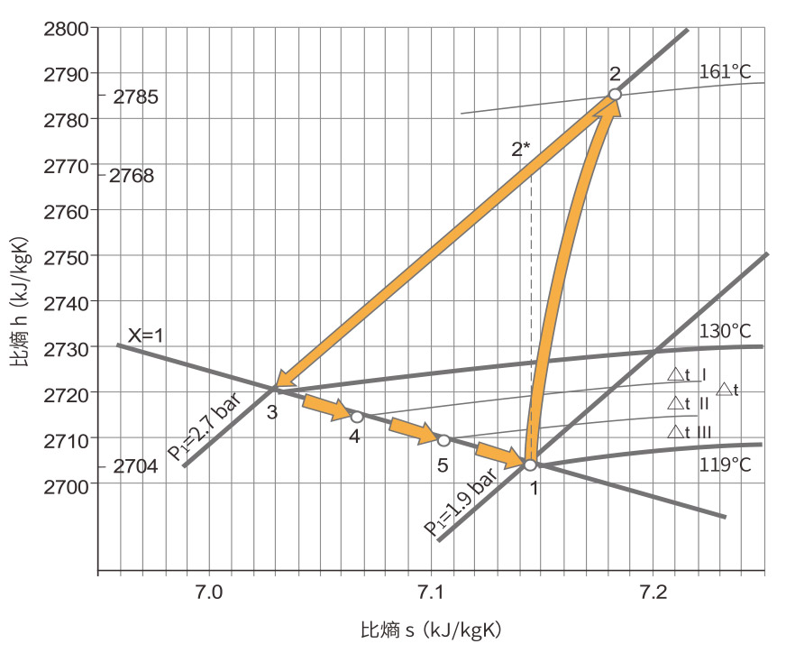
△The MVP operating principle is illustrated in Enthalpy-Entropy Diagram as shown on the left. Being compressed by the compressor, the vapor changes from the Saturated State 1 to State 2 after temperature and pressure rises, and then joins the heating materials in the evaporator to release heat and cool down until to the pressure 1 state.
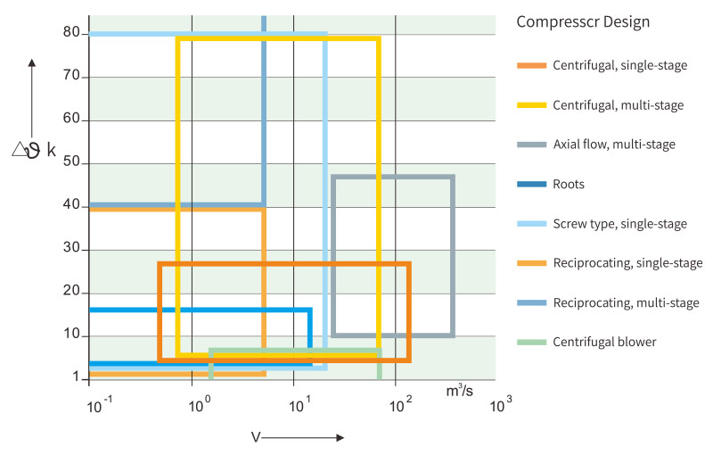
△Functional range of the compressor used for vapor recompression as per manufacturer’s data (water vapor condensation temperature rise △ k at 1 bar and 100℃ initial state)
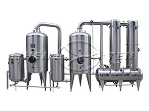
MVR-OSLO Continuous Crystallizer
A MVR-OSLO continuous crystallizer comprises MVR system and OSLO crystallization system. The OSLO crystallizer was proposed by a Norwegian named Jeremiassen in 1930s, which is often called Krystal crystallizer or size-grading crystallizer.After entry into the system, the liquid flows into the evaporator by means of the circulating pump and is heated to evaporate; the gas then enters into the evaporation chamber; the concentrate separated from the secondary vapor is delivered through the central down-line to the bottom where crystals grow and then passes upwards through the crystal fluid bed to avoid over saturation. In doing so, crystals in the crystal bed grow and are discharged from the outlet when their sizes meet the required ones. The secondary vapor increases its temperature and pressure through MVR system and is then recovered for subsequent uses. This design makes full use of the latent heat during evaporation and therefore achieves the energy-saving goal.

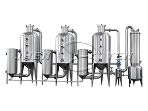
MVR-DTB Continuous Crystallizer
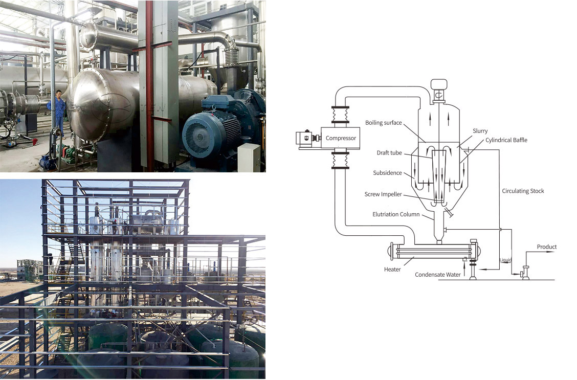
A MVR-DTB continuous crystallizer comprises MVR system and DTB crystallization system. DTB crystallizer is highly efficient and years of observation of the operating performance demonstrates that this crystallizer is good at performance, able to form larger size crystals (size 600-1200um), highly productive, and not easy to encrust, and therefore has become a main form of continuous crystallizers. It can be used for vacuum cooling, evaporation, and reaction-method crystallizations. In the middle part of the DTB crystallizer there is a draft tube guarded by a circular baffle at its perimeter. Driven by the screw propeller, the fluid rises inside the tube to the edge, then turns back to the bottom along the annular channel formed by the draft tube and the baffle, and is re-sucked into the draft tube on the bottom. The cycle repeats endlessly, creating good a condition for crystallization. This kind of crystallizer is capable of clearing mother liquor overflow and eliminating fine grains. When coupled with the MVR, the crystallizer will not only get crystals of better granularity but also be more power efficient.
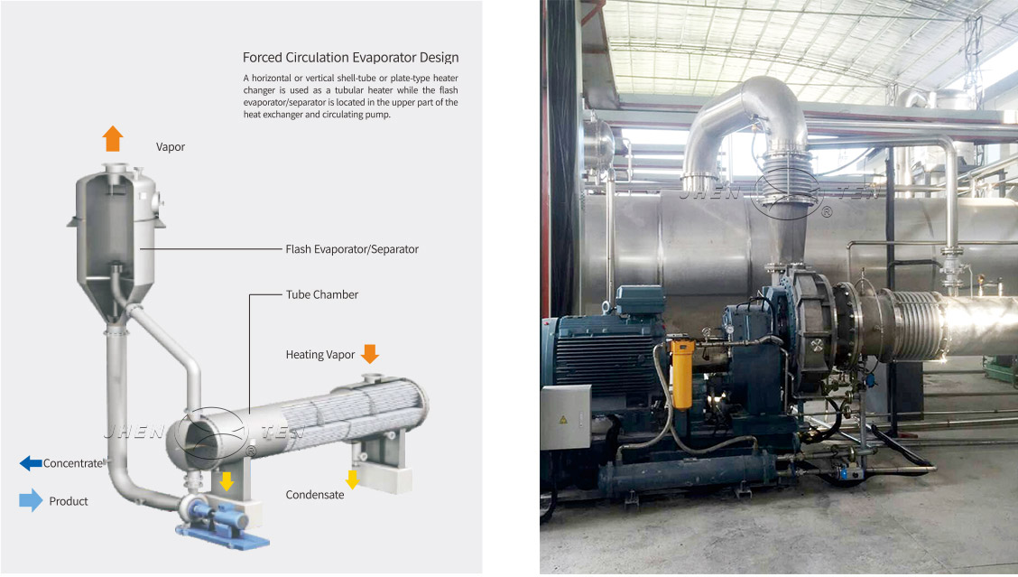
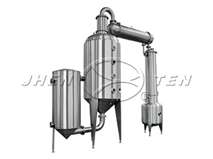
MVP Falling-film Evaporator
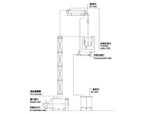
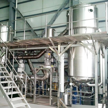
Principle: The material enters into the top part of the falling-film evaporator through the material circulating pump and flows in a membranous manner by mans of the distribution plate. The primary vapor is the fresh steam heated outside the pipe, boiling the solution to generate the secondary vapor which then is sucked in by the compressor; after pressurization, the secondary vapor has its temperature increased and flows into the heating chamber as a heating source to join the circulating evaporation process. When normally started up, the compressor will suck in the secondary vapor and heat the vapor by means of pressurization. It is in this way that the circulating evaporation cycle is then permanently maintained. The moisture evaporated eventually becomes the condensed water and is discharged. No supplement of additional fresh steam is required when the system comes to the stable.
Advantages of MVP Falling-film Evaporator
1.Short retention time, no aroused degradation of heat sensitive materials;2.Bigger het transfer coefficient during evaporation due to the film like contour and faster fluid flow-rate; 3.Small pressure drop and therefore nearly constant pressure and temperature at the heat exchange side, requiring almost no or only minimal sensible heat;4.An even lower difference in temperature is allowed as the process stream flows only under the gravity rather than under temperature difference;5.Less retentate in the plant;6.Convection boiling, subject to little effect of the tube surface state on the boiling process.